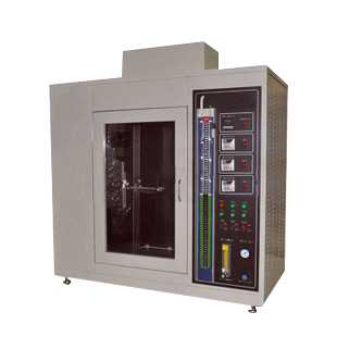
Horizontal and vertical flammability tester is mainly used to measure the combustion performance of plastic, rubber or film under the specified fire source, so as to judge its fire resistance level. It is not only suitable for the research, production and quality inspection departments of electrical and electronic plastic or rubber products such as lighting equipment, low-voltage electrical appliances, household appliances, motors, tools, instruments and electrical connectors and their components, but also for insulating materials, engineering Plastic, firestop material type approval or other solid combustible material
Technical Parameters:
Calibration purpose and requirements
The calibration of the test flame is the most basic guarantee for the test to ensure the reliability of the test. The test requires a 50w flame height of 20±1mm, the outer yellow flame height of the 500w flame is 125mm, and the inner blue flame height is 40mm; use the flame to heat the copper block, and the time required for the warm copper block to rise from 100 degrees to 700 degrees is required. The 50W test flame is 44±2s, 500W test flame is 54±2s
Specific test method
1. Gas burner
A modified Bunsen burner provides non-pajama test kits. Burner includes flame altimeter and light guide. For children's pajamas test kits are provided with sloped side burners mounted on the side walls of the test chamber.
2. Air connection
The gas mixture shall be methane, 99% pure, or as specified in the applicable test method. If using a side burner, connect the gas supply line directly to the burner inlet through a customer-supplied pressure regulator. If using a Bunsen burner, connect your gas supply to a manual gas control unit and connect the unit's output wire to the burner inlet
3. The position and flame height of the Bunsen burner
Position the burner so that the center of the burner barrel is directly below the center of the specimen
On the burner, relative to the pilot tube, there is a metal flame height gauge spaced 13 mm (1/2 in) from the barrel and extending above the burner. The rod has two 8mm (5/16in) tips with marks spaced 19mm (3/4in) and 38mm (1 1/2in) above the top of the burner. Use this gauge when adjusting burner flame heights in accordance with applicable test methods.
4. Burner operation
To use the side burner for the test: hang the empty sample holder from the support rod of the VFC chamber, and clamp the rear edge of the holder to the holder rail protruding from the rear wall of the chamber. Place the burner tube directly below the center of the specimen and adjust the position of the stop ring on the burner (outside of the burner). Slide the burner out (to the right) into position and light. According to the test method, adjust the flame height of the burner according to the flame height gauge on the inner wall of the combustion chamber. As previously described, remove the empty specimen holder and hang the loaded specimen holder in the cavity. Close the hatch and conduct the test according to the applicable test method
Set the control mode switch to the automatic position.
2. Prepare your test sample and mount it in the appropriate holder within the instrument's test chamber.
3. If applicable, place the burner under the sample according to your test method.
4. On the AGC, open the main gas shutoff valve by lifting the toggle lever up until the lever points out from the panel.
NOTE: Opening this valve allows gas to enter the pilot burner, the pilot must be ignited immediately.
5. Ignite the pilot burner.
6. Close the instrument compartment door.
7. Press the timer reset button below the elapsed time display on the AGC. If the display is counting, press the timer start button to turn it off. Press the timer reset button to make the display zero.
8. To start the test, simultaneously press the burner start button and the timer start button on the AGC. (Correct operation will be indicated by the illumination of both switches. If neither is illuminated, press the chrono start switch to extinguish the light and press the chrono reset button below the run time display. Simultaneously press both start switches again to start test.
9. When the timer indicates 15 seconds (HMV) or 12 seconds (VFC), the burner will go off. You can let the elapsed time display keep counting and stop it as desired by pressing the timer start button. You can also stop it with the timer start button, reset it to zero with the timer reset switch, and restart it by pressing the timer start button to time a burn event. Press the timer start button again to stop it.
10. Time the desired event using the run time display described above or use the handheld event timer provided by AGC.
11. Additional tests can be performed by repeating steps 6-8 above.
12. When you are finished using the AGC, always close the main gas shutoff valve by pushing the toggle lever to the fully down position (do not point out of the panel). Cut off the gas supply to your tank or equipment. AGC is turned off electrically by moving the control mode switch to the center position.
Tag:
horizontal flammability tester,vertical flammability tester,flammability tester,ul94 vertical and horizontal flammability tester,horizontal vertical flammability tester,horizontal & vertical flammability tester,horizontal and vertical flame tester,flammability testing equipment,vertical flammability chamber,flammability test chamber,fabric vertical flammability tester
ps: (WLJCDM809)
https://www.standard-groups.com/en/FlammabilityTesting/
http://burningtester.com/products/textile_flammability_tester/476.html
评论
发表评论